
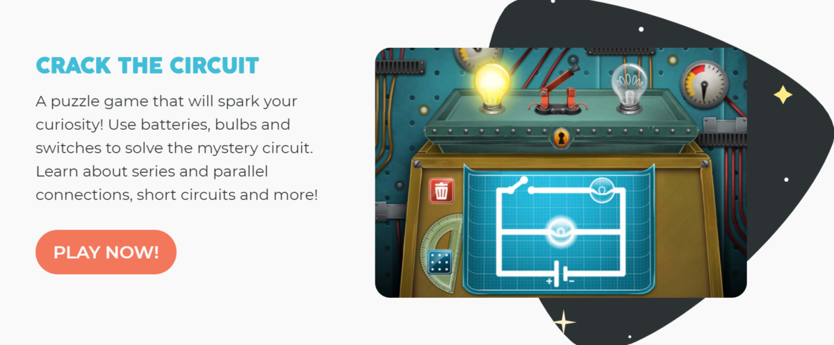
I must say a few minutes ago before writing this blog, I felt I was an electrical engineer just by solving 18 relatively challenging electric circuit-related puzzles. While writing, my anxiety is reducing so getting back to the topic. Currently, I am learning about Electricals, Circuits, and all that sort of jazz in science. On the 5th of October, my Science teacher Ms. Kelly shared a cool online game/puzzle on an electric circuit with my class.

This game can be found at https://www.universeandmore.com/crack-the-circuit/. According to the website, the game was developed by Matthew Blackman a public school AP Physics Teacher. Surely you can get the feel of reliability.
Advanced Placement (AP)
In the United States, Advanced Placement (AP) Physics collectively refers to the College Board Advanced Placement Program courses and exams covering various areas of physics.
en.wikipedia.org › wiki › AP_Physics
After solving the puzzles, I was curious to check if there were any solutions given on the internet. Surprisingly I couldn’t find any youtube videos or articles on it, so I thought why not explain my solution. This way scholars can take a peek to get an idea about the solutions. And personally, I can revise once more.
Answers:
I strongly advise you to make an attempt to solve, before looking into the answers.
#1
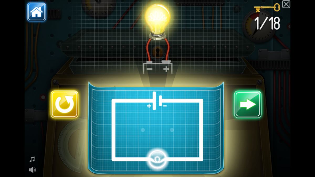
- Insert a Battery
- Insert a Bulb
- Draw a wire from the Negative Terminal to the Bulb
- Draw a wire from the bulb to the Positive Terminal
#2
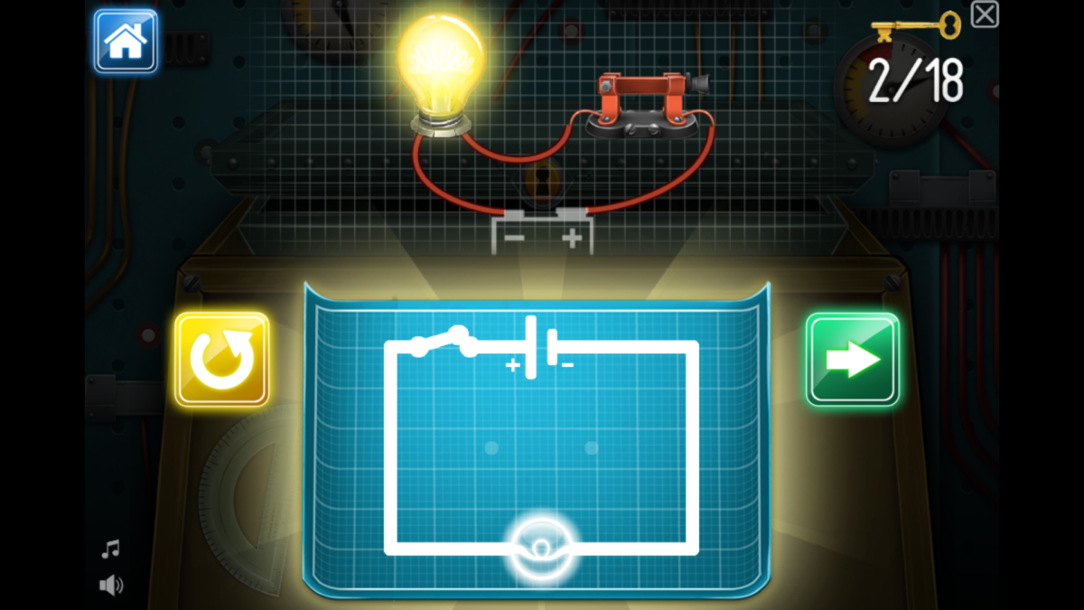
- Insert a Battery
- Insert a Bulb
- Insert a Switch
- Draw a wire from the Negative Terminal to the bulb
- Draw a wire from the bulb to the Switch
- Draw a wire from the switch to the Positive Terminal (In my case I didn’t need to because I have placed the switch just beside the Positive Terminal)
#3
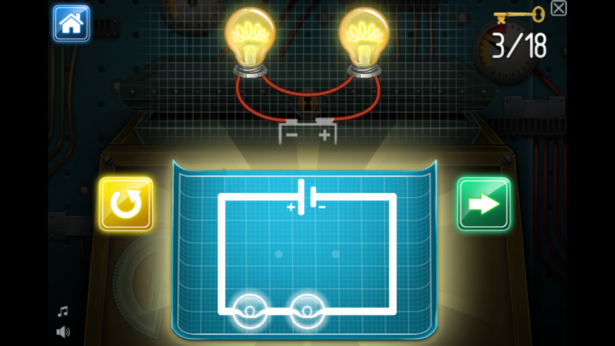
- Insert the Battery
- Insert two Bulbs
- Draw a wire from the Negative Terminal to the x bulb
- Draw a wire from the x bulb to y bulb
- Draw a wire from the y bulb to the Positive Terminal
#4
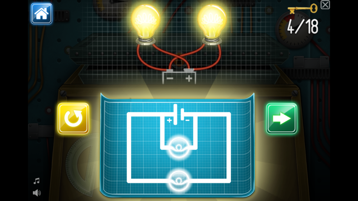
- Insert the Battery
- Insert two Bulbs
- Draw a wire from the Negative Terminal to the x bulb
- Draw a line from the x bulb to the Positive Terminal
- Draw a wire from the Negative Terminal to the y bulb
- Draw a wire from the y bulb to the Positive Terminal
#5
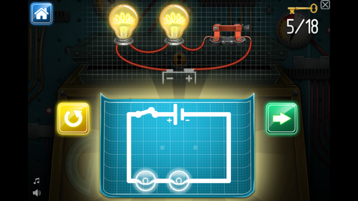
- Insert a Battery
- Insert a 2 Bulbs
- Insert a Switch
- Draw a wire from the Negative Terminal to the x bulb
- Draw a wire from the x bulb to the y bulb
- Draw a wire from the y bulb to the Switch
#6
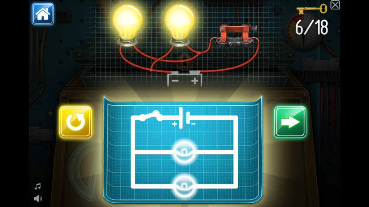
- Insert the Battery
- Insert two Bulbs
- Draw a wire from the Negative Terminal to the x bulb
- Draw a line from the x bulb to the Switch
- Draw a wire from the Negative Terminal to the y bulb
- Draw a wire from the y bulb to the Switch
- Draw a wire from the Switch to the Positive Terminal (In my case I didn’t need to because I have placed the switch just beside the Positive Terminal)
#7
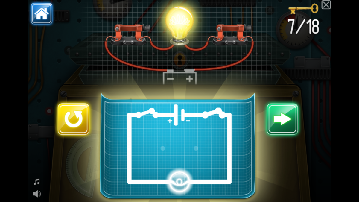
- Insert a Battery
- Insert 2 Switches
- on the Negative Terminal
- on the Positive Terminal
- Draw a wire from the Negative Terminal to switch
- continue the wire to the Bulb
- Draw a wire from the Bulbt to the Switch (near the Positive Terminal)
- Draw a wire to connect the switch to Positive Terminal (If needed)
#8
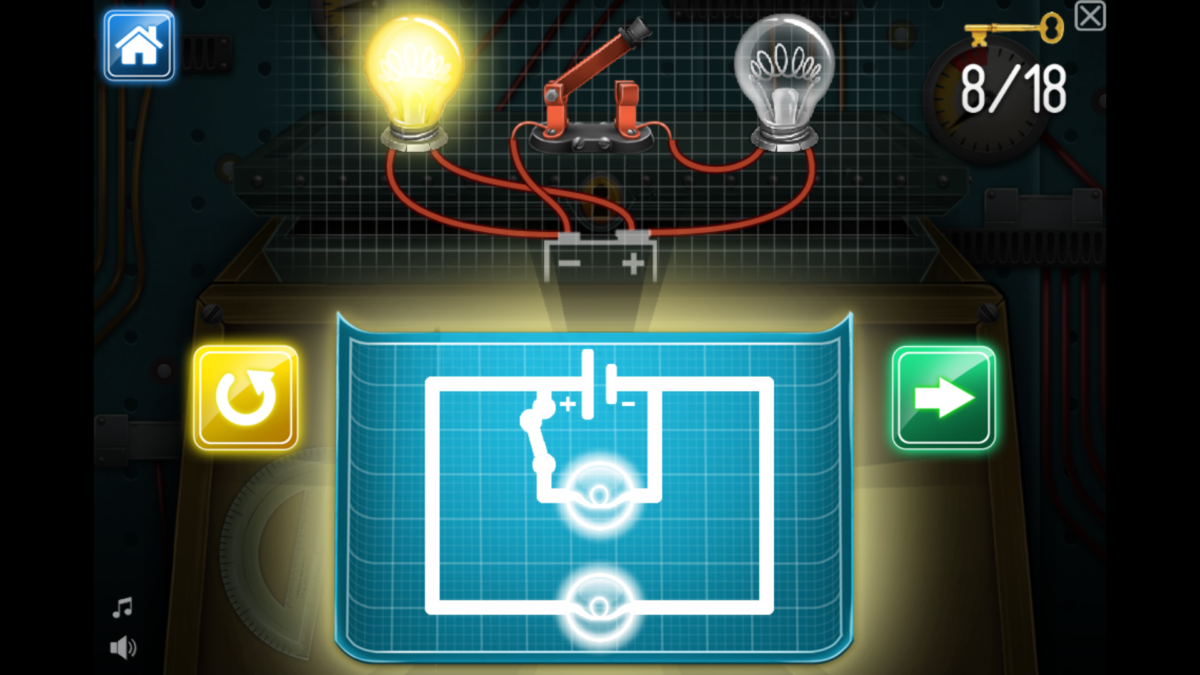
- Insert a Battery
- Insert 2 Bulbs
- Insert a Switch
- Draw a wire from the Negative Terminal to the x bulb
- from the bulb, draw wire to the switch
- connect the switch with the Positive Terminal
- Draw a wire from the Negative Terminal to the y bulb
- continue the wire, attach it with the Positive Terminal
#9
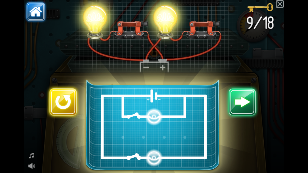
- Insert a Battery
- Insert 2 Bulbs
- Insert a Switch
- for x bulb
- for y bulb
- Draw a wire from the Negative Terminal to the
- x Bulb
- continue the wire to the switch up till the Positive Terminal
- y Bulb
- continue the wire to the switch up till the positive terminal
- x Bulb
#10
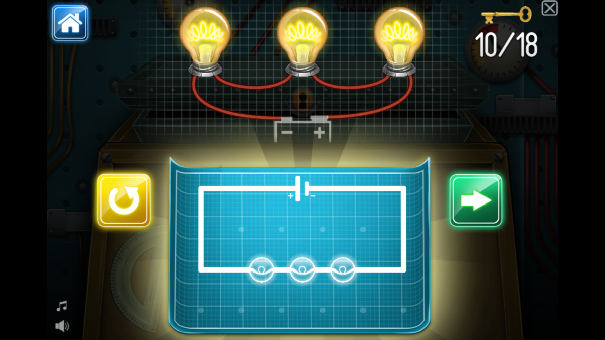
- Insert a Battery
- Insert 3 Bulbs
- Draw a wire from the Negative Terminal running through all three bulbs, connecting to the Positive Terminal
#11
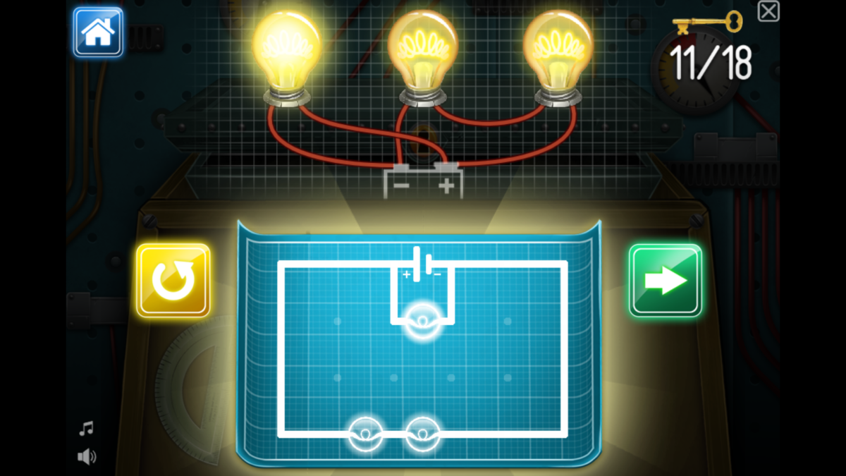
- Insert a Battery
- Insert 3 Bulbs
- Draw a wire from the Negative Terminal to
- x Bulb, continue till it connects with the Positive Terminal
- y and z bulb, till it connects with the Positive Terminal
#12
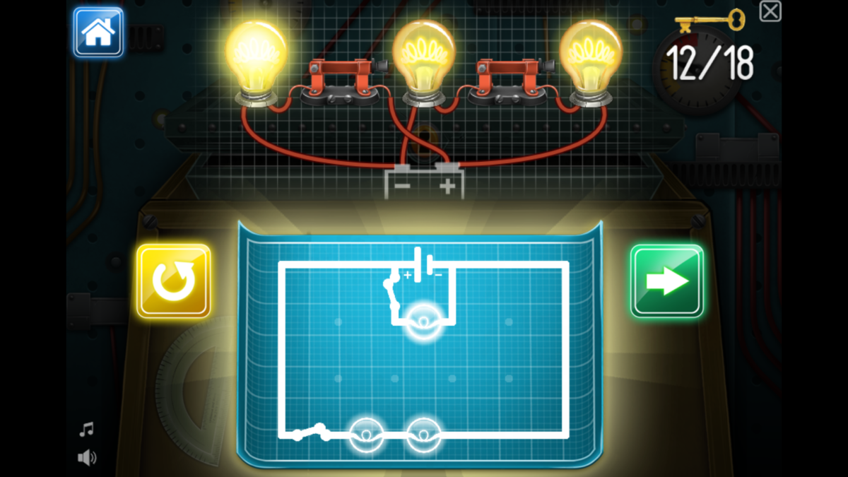
- copy steps from #11
- Insert switch between
- x bulb and the positive terminal
- y and z bulb and the positive terminal
#13
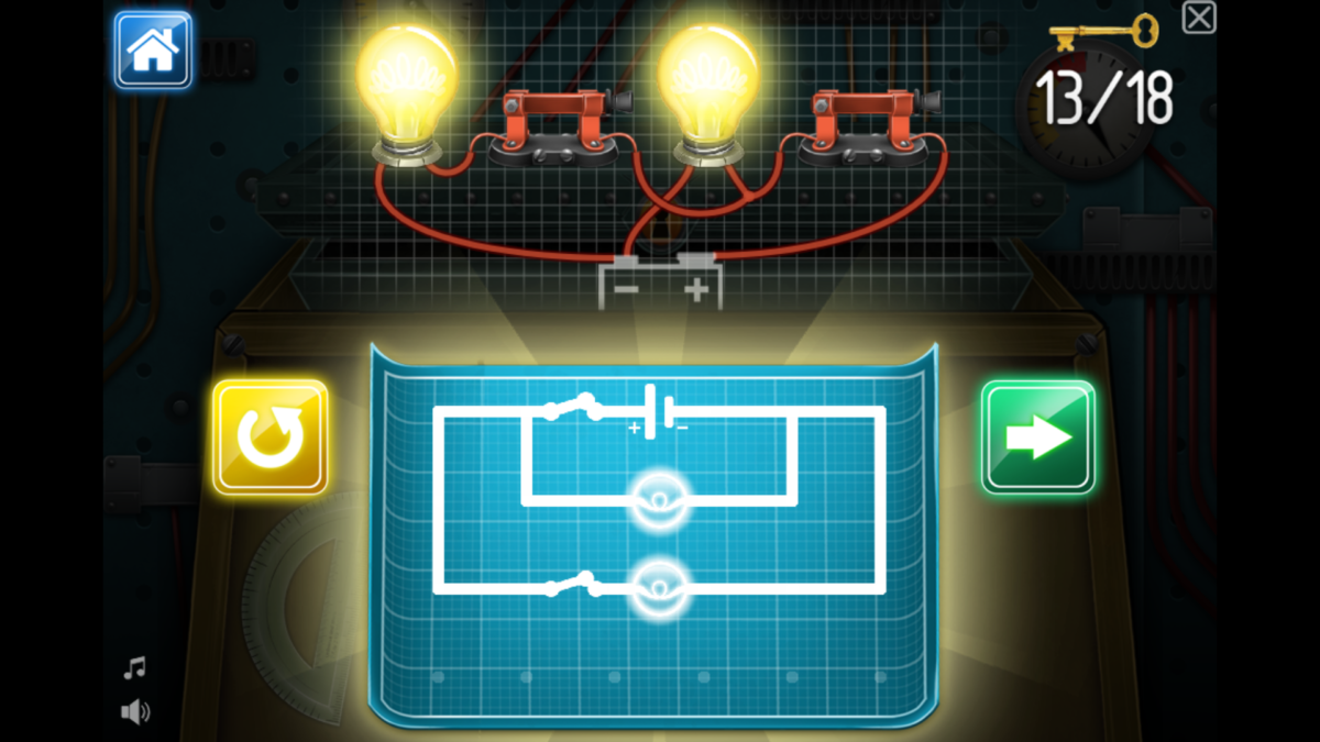
- Insert a Battery
- Insert 2 Bulbs
- Draw a wire from the Negative Terminal to
- x bulb,
- add the switch to connect to the positive terminal
- y bulb
- add the switch
- draw the wire from the y switch to the x switch
- x bulb,
#14
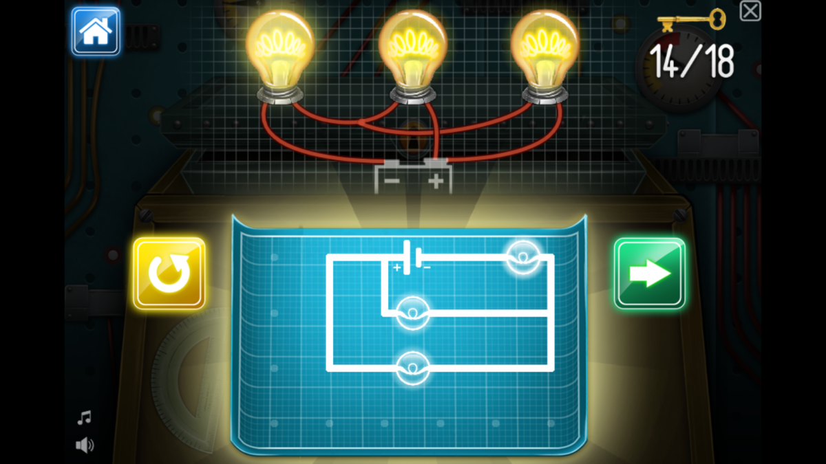
- Insert a Battery
- Insert 3 Bulbs
- Draw a wire from the Negative Terminal to
- x bulb,
- continue wire thru _________ till Positive Terminal
- y Bulb
- z Bulb
- continue wire thru _________ till Positive Terminal
- x bulb,
#15
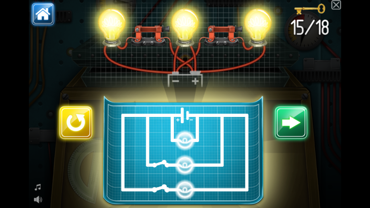
- C’mon friends, see the picture!
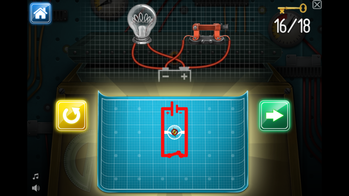
#16
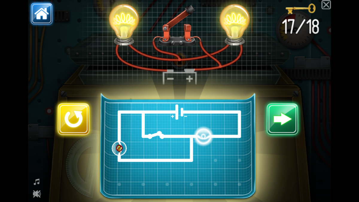
#17
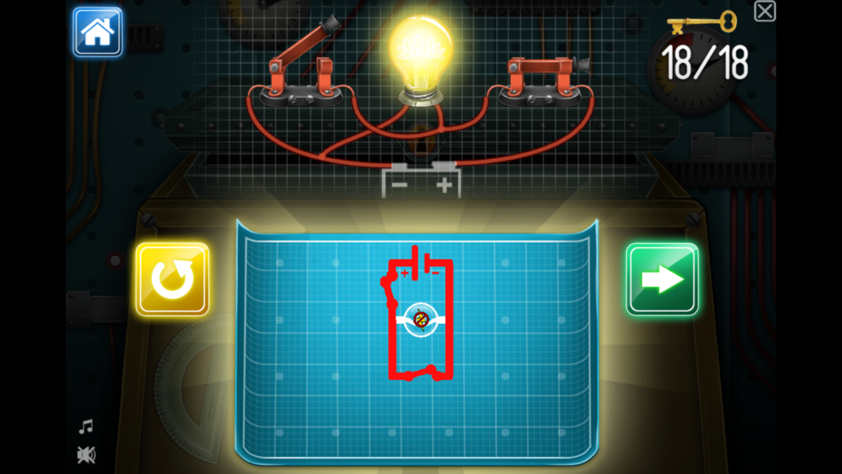
#18
Phew, that was quite an exhaustive blog. I appreciate your patience if you reached this far.
I am excited to present this blog to my classmates and Ms. Kelly. Time will tell whether this aritcle will be helpful or not. Fingers crossed….